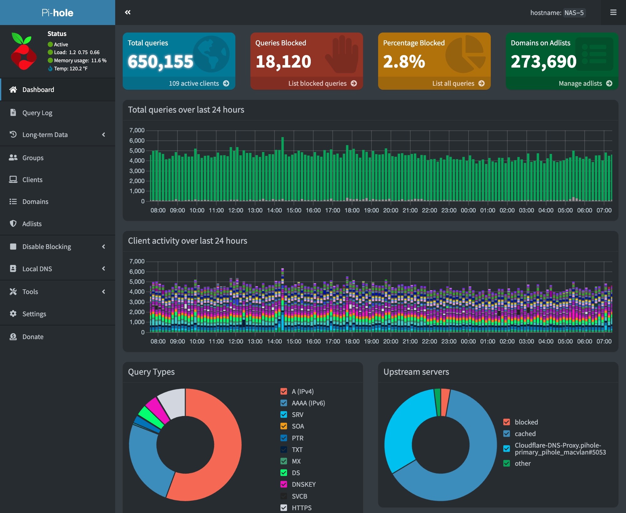
We have set up a Raspberry Pi 5 system to run a third PiHole DNS server in our network. This ensures that DNS services are available even if our other servers are down.
To make this PiHole easy to manage, we configured our Raspberry Pi to run Docker. This enables us to manage the PiHole installation on the Pi from the Portainer instance used to manage our systems running docker.
We are also running the Traefik reverse proxy. Traefik is used to provide an SSL certificate for our PiHole.
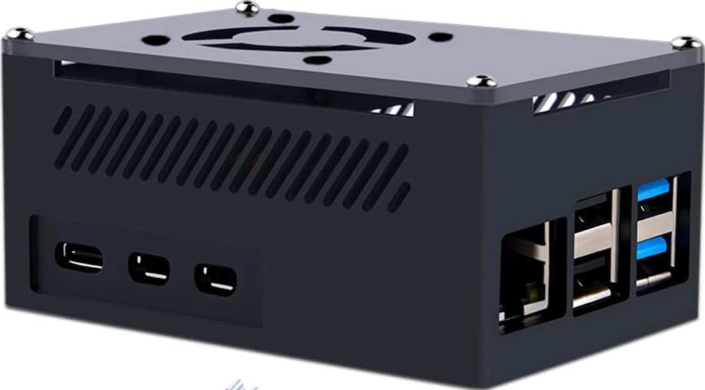
Raspberry Pi Hardware
Raspberry Pi Docker Host
Our docker host consists of a PoE-powered Raspberry Pi 5 system. The hardware components used include:
Raspberry Pi 5 8GB Single Board 2.4GHz Quad-core SBC
We are running the 64-bit Lite version (no GUI desktop) of Raspberry Pi OS. The configuration steps on the initial boot include:
Setting the keyboard layout to English (US)
Setting a unique user name
Setting a strong password
After the system is booted, we used sudo raspi-configto set the following additional options:
Updated raspi-config to the latest version
Set the system’s hostname
Enable ssh
Set the Timezone
Configure predictable network names
Expand the filesystem to use all of the space on our flash card
Next, we did a sudo apt update && sudo apt dist-upgrade to update our system and rebooted.
The RPi 5 works well with the PoE HAT we are using. The RPi5 booted up with the USB interfaces in low-power mode. The PoE HAT provides enough power to enable USB boot, so we added the following to bring our RPi up in full power USB mode:
$ sudo vi /boot/firmware/config.txt

[all]
# Enable RPi 5 to provide full power to USB
usb_max_current_enable=1
:wq

# After rebooting, check USB power mode
$ vcgencmd get_config usb_max_current_enable
usb_max_current_enable=1
Finally, we created and ran a script to install our SSH keys on the system, and we verified that SSH access was working. With this done, we ran our ansible configuration script to install the standard set of tools and utilities that we use on our Linux systems.
Mail Forwarding
We will need to forward emails from containers and scripts on the system. To do this, we set up email forwarding using the procedure here.
Docker/Docker Compose Installation
Installing Docker and the Docker Compose plugin involves a series of command line steps on the RPi. To automate this process, we created a script that runs on our Ubunutu Admin server. The steps required for these installations are covered in the following video:
Steps to install Docker and Docker Compose on a Raspberry Pi
Some important adjustments to the steps in the video included:
Installed the Docker Compose plugin instead of Docker Compose. The procedure to install the plugin can be found here.
The installation can be verified at the end with the following commands:
# docker --version
# docker compose version
# docker run hello-world
Portainer Agent
We installed the Portainer Edge agent using the following command, which is run on the RPi:
These applications are installed via custom scripts, and Docker Compose using a single stack. Our combined stack was created using a combination of the information in the following videos:
We must update our piHole block list by doing a Gravity pull. We do this daily via a cron job. This can be configured on the RPi host using the following commands –
# Edit the user crontab
sudo crontab -u <user-id> -e

# The following to the user crontab
min hr * * * su ubuntu -c /usr/bin/docker exec pihole pihole -g | /usr/bin/mailx -s"RPi Docker - Gravity Pull" your-email@mydomain.com
Cloudflare DDNS
We host our domains externally on Cloudflare. We use Docker containers to keep our external IP address up to date in Cloudflare’s DNS system. You can learn about how to set this up here.
Watchtower
We are running the Watchtower container to keep our containers on our RPi Docker host up to date. You can learn more about Watchtower and how to install it here.
Backups
We back up our Raspberry Pi Docker host using Synology ActiveBackup for business running on one of our Synology NAS drives.
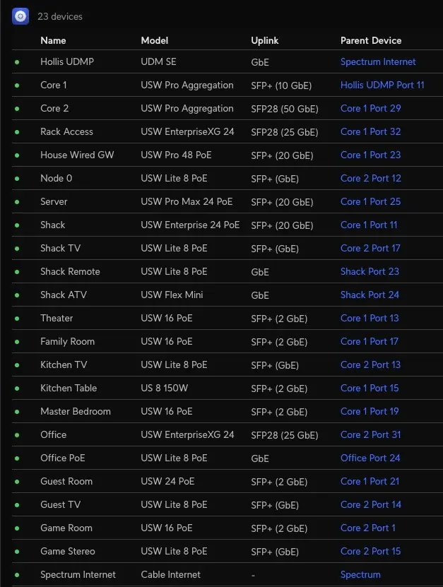
We use UniFi equipment throughout. We chose the UniFi platform for our second-generation home network primarily for its single-plane glass management and configuration capabilities.
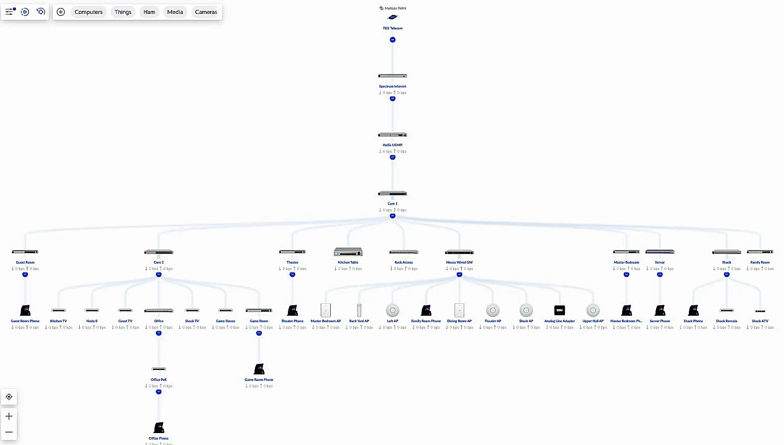
Network Structure
Network Structure
The image above shows our network’s structure. Our Network is a two-tiered structure with a core based upon high-speed 25 GbE capable aggregation switches and optically connected edge switches. We have installed multiple OM4 fiber multi-mode fiber links from the core to each room in our house. The speed of these links ranges from 1 Gbps to 25 Gbps, with most connections running as dual-fiber LACP LAG links.
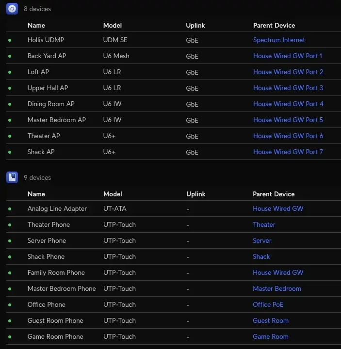
Access Layer
At the top layer, redundant Internet connections provide Internet Access and ensure that we remain connected to the outside world.
Firewall, Routing, and Management Layer
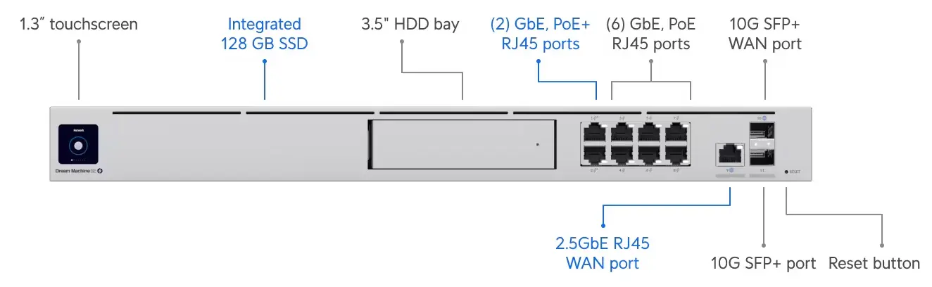
UniFi Dream Machine Pro SE
Our network’s firewall and routing layer implement security and routing functions using a UniFi UDM Pro router and firewall.
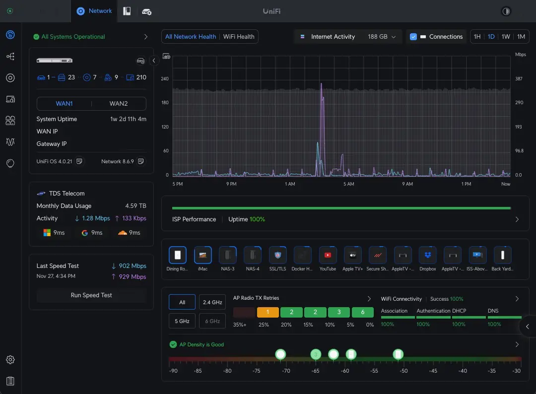
Home Network Dashboard
The UDM also provides a single-pane-of-glass management interface. All configuration functions are performed via the GUI provided by the UDM.
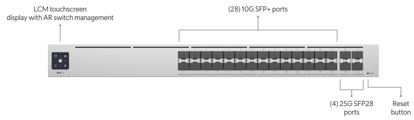
Core Aggregation Layer
UniFi High-Capacity Aggregation Switch
The core layer uses a pair of high-capacity Aggregation Switches to provide optical access links to all of the switches in our network’s edge layer. We also include a high-speed 10 GbE wired ethernet switch at this layer. All of our storage devices and servers are connected directly to the core layer of our network to maximize performance and minimize latency.
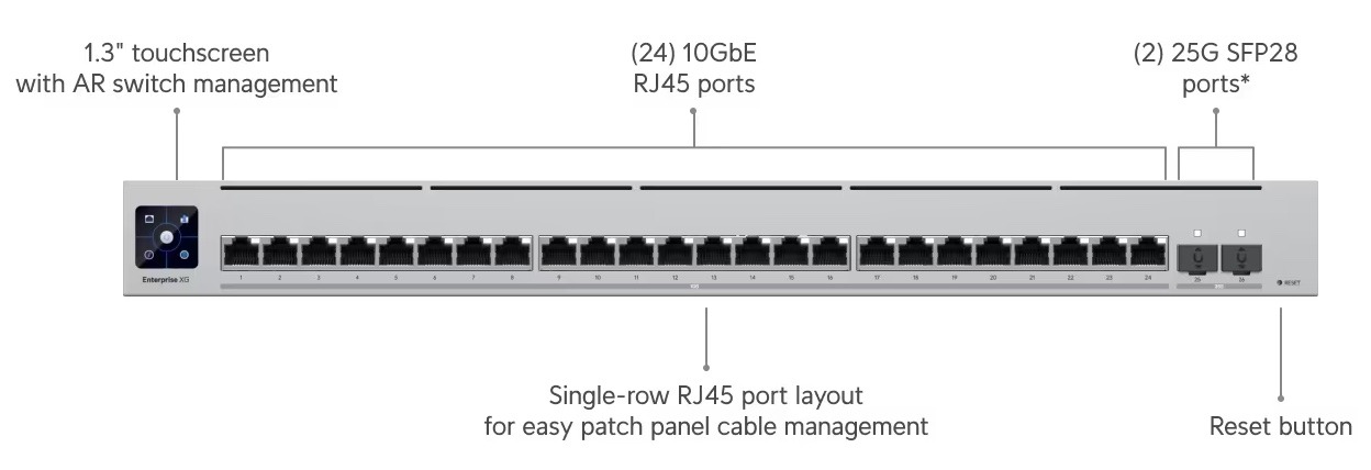
Edge Connectivity Layer
Example UniFi High-Speed Edge Switch
The edge layer uses various switches connected to the core layer, combining 25 GbE, 10 GbE, and 1 GbE optical links. Many of these links are built using pairs of optical links in an LACP/LAG configuration.
UniFi Firewall/Router, Core, and Edge Switches In Our Network
Our edge switches are deployed throughout our home. We use a variety of edge switches in our network, depending on each room’s connectivity needs.
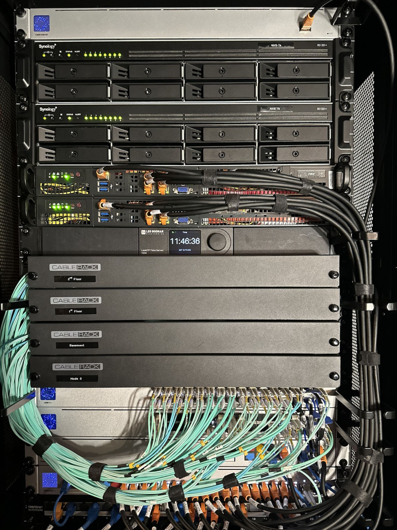
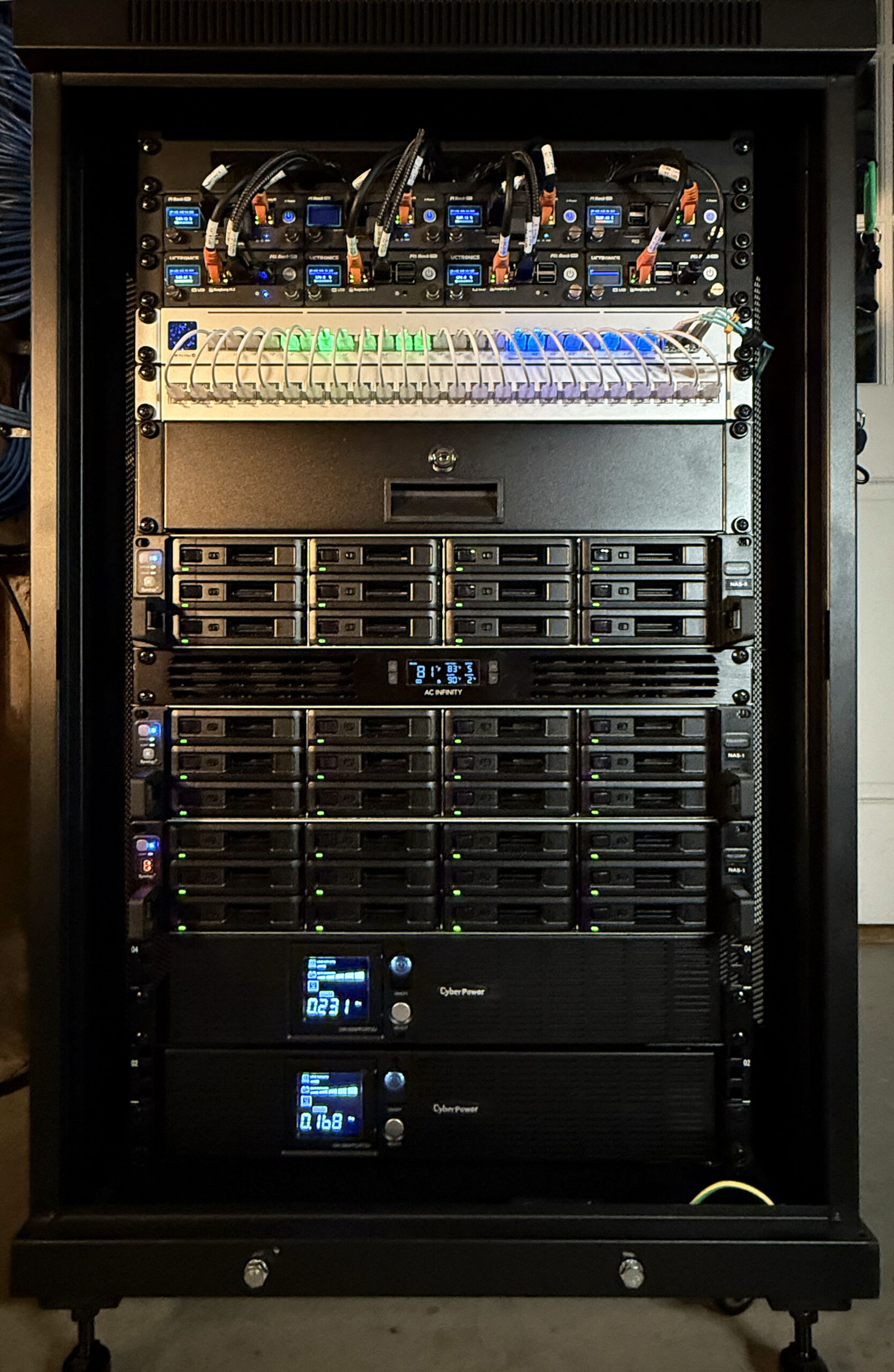
Main NAS Storage Rack – Synology RS2421RP+ and RX1217RP+ NAS Drives
We use a variety of NAS drives for storage in our Home Lab.
Device
Model
Storage Capacity
RAID Level
Purpose
Network Interface
NAS-1
Synology RS2421RP+/RX1223RP
272 TB HDD
RAID-6
Backups and Snapshot Replication
Dual 10 GbE Optical
NAS-2
Synology RS2421RP+
145 TB HDD
RAID-6
Video Surveillance and Backups
Dual 10 GbE Optical
NAS-3
Synology RS1221+/RX418+
112 TB HDD/SSD
RAID-5&6
Media Storage and DVR
10 GbE Optical
NAS-4
Synology RS2421RP+/R1223RP
290 TB HDD
RAID-6
Backups and Snapshot Replication
Dual 10 GbE Optical
NAS-5
Synology FS2017+
17 TB SSD
RAID F1
High-Speed Storage for Video Editing & TimeMachine BUs
25 GbE Optical
NAS-6
Synology DS1621xs+/DX517
116 TB HDD
RAID-5
General Purpose Storage
Dual 10 GbE Optical
NAS-7
Dual Synology RP1221+ in High-Availability configuration
24 TB SSD
RAID-5
VM and Docker Volumes
10 GbE Interface
NAS-10
Dell Server-based File Server using ZFS
23 TB SAS SSD
RAID-10
High-Speed Scratch Storage
25 GbE Optical
NAS-11
Raspberry Pi NAS
2 TB NVMe
n/a
Experimentation
2.5 GbE
NAS-12
Raspberry Pi NAS
3.5 TB SSD
RAID-0
Experimentation
2.5 GbE
The table above lists all of the NAS drives in our Home Lab. Most of our production storage is implemented using Synology NAS Drives. Our total storage capacity is just over 1 Petabyte. Our setup also provides approximately 70 TB of high-speed solid-state storage.
Systems with Dual Optical interfaces are configured as LACP LAGs to increase network interface capacity and improve reliability.
Hardware and Power
We have moved to mostly rack-mounted NAS drives to save space and power. The picture above shows one of our racks which contains Synology NAS drives. We have also opted for Synology Rack Mount systems with redundant power supplies to improve reliability. Our racks include dual UPS devices to further enhance reliability.
Basic Setup and Configuration
We cover some details of configuring our Synology NAS devices running DSM7.2 here.
Multiple VLANs and Bonds on Synology NAS
Our NAS devices use pairs of ethernet connections configured as 802.3ad LACP bonded interfaces. This approach improves reliability and enhances interface capacity when multiple sessions are active on the same device. DSM supports LACP-bonded interfaces on a single VLAN. This can be easily configured with the DSM GUI.
A few of our NAS drives benefit from multiple interfaces on separate VLANs. This avoids situations where high-volume IP traffic needs to be routed between VLANs for applications such as playing media and surveillance camera recording. Setting this up requires accessing and configuring DSM’s underpinning Linux environment via SSH. The procedure for setting this up is explained here and here.
Creating a RAM Disk
You can create a RAM disk on your Synology NAS by creating a mount point in one of your shares and installing a shell script to run when the NAS boots to create and mount a RAM disk. If your mount point is in a share on your Storage Pool on volume1 named Public and is called tmp then –
#!/bin/sh
mount -t tmpfs -o size=50% ramdisk /volume1/Public/tmp
will create a RAM disk that uses 50% of the available RAM on your NAS and is accessible as /volume1/Public/tmp by packages running on your NAS. The RAM disk will be removed when you reboot your NAS so you’ll need to run the command above each time your NAS boots. This can be scheduled to run on boot using the Synology Task Scheduler.