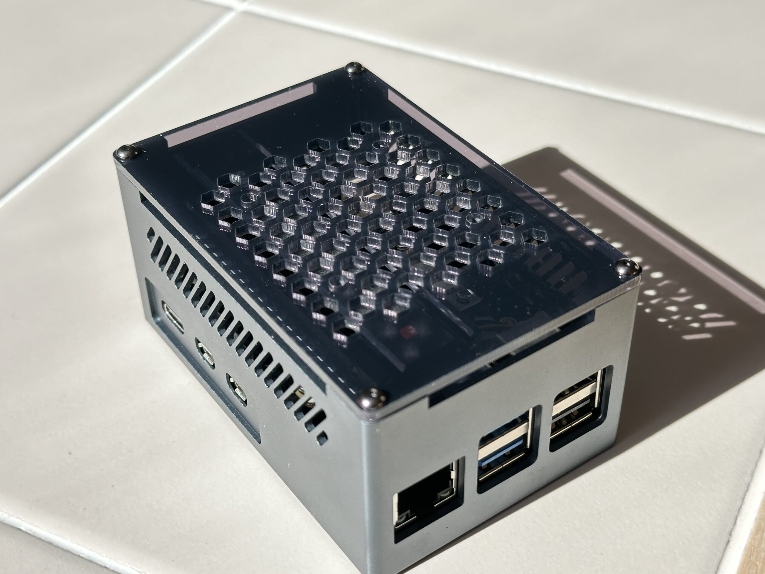
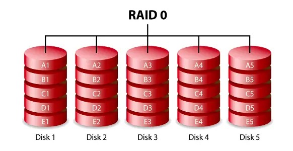
We’ve built a second NAS and Docker environment using another Raspberry Pi 5. This NAS features four 2.5 in 960 GB SSD drives in a RAID-0 array for fast shared storage on our network.
Raspberry Pi NAS Hardware Components
We use the following components to build our system –
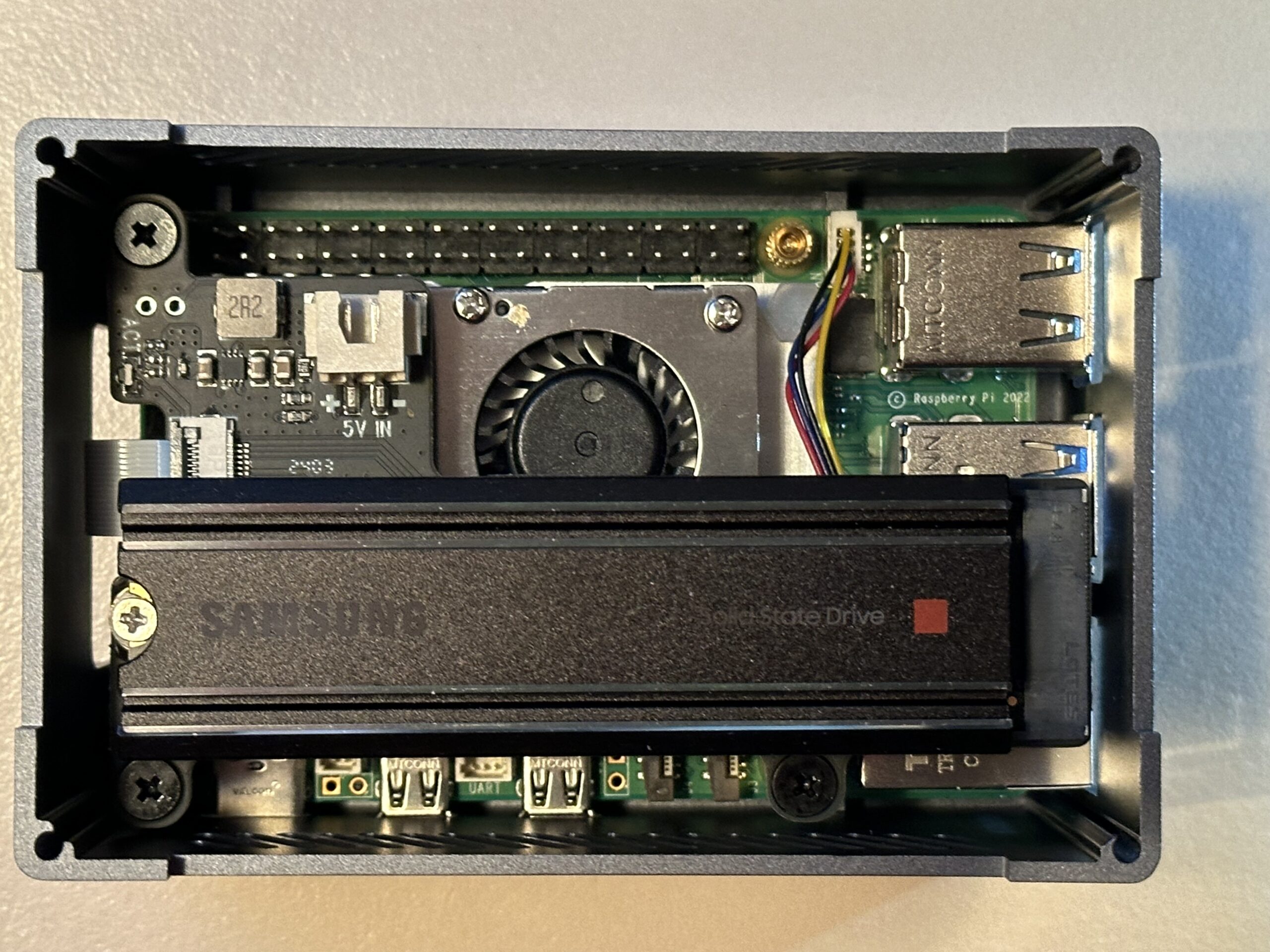
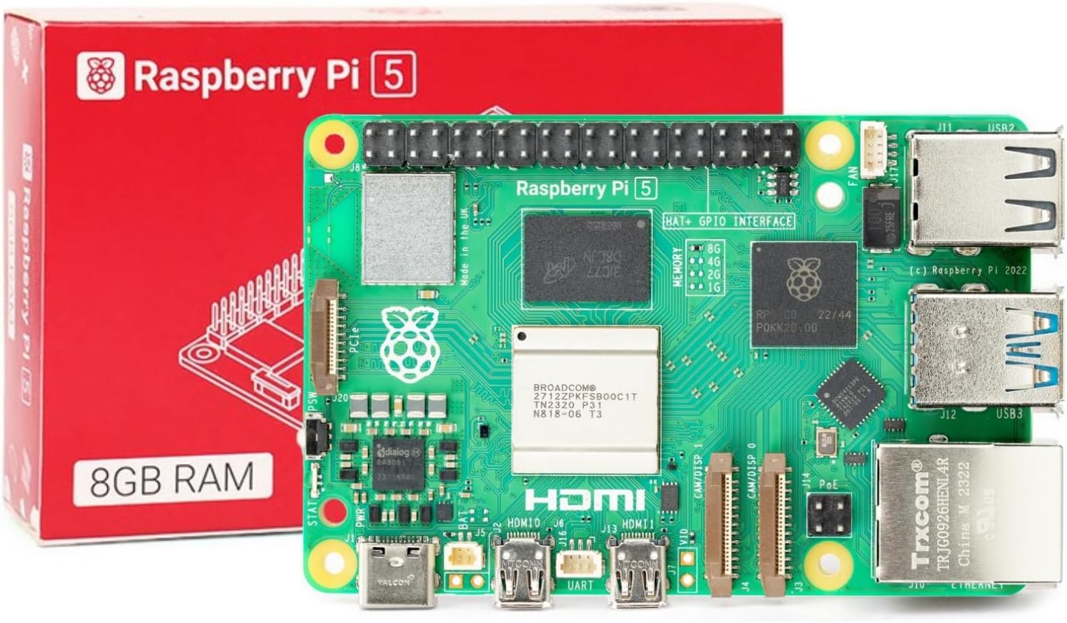
- Raspberry Pi 5 SBC with 8 GB memory
- An Active Cooler for the Raspberry Pi 5
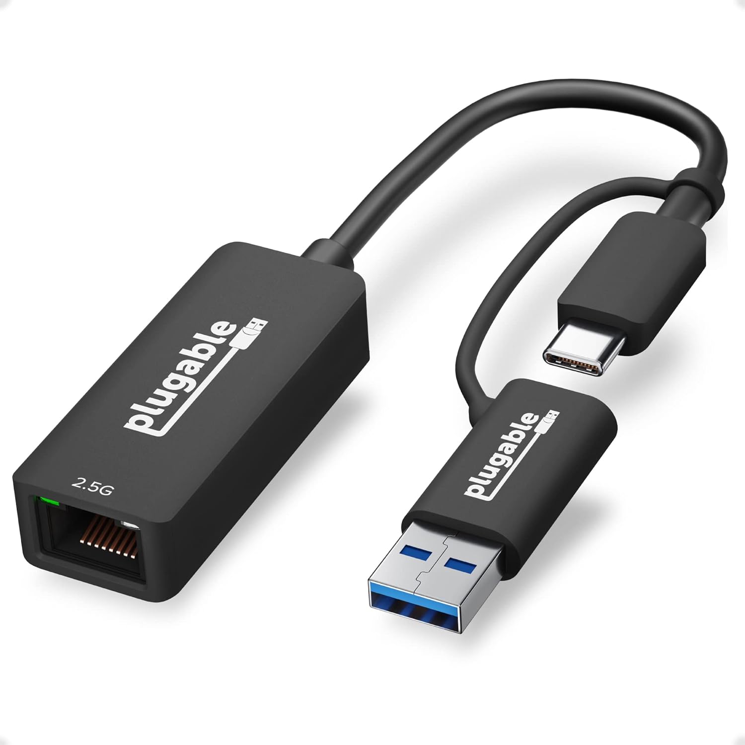
- Plugable 2.5GB USB-C Ethernet Adapter
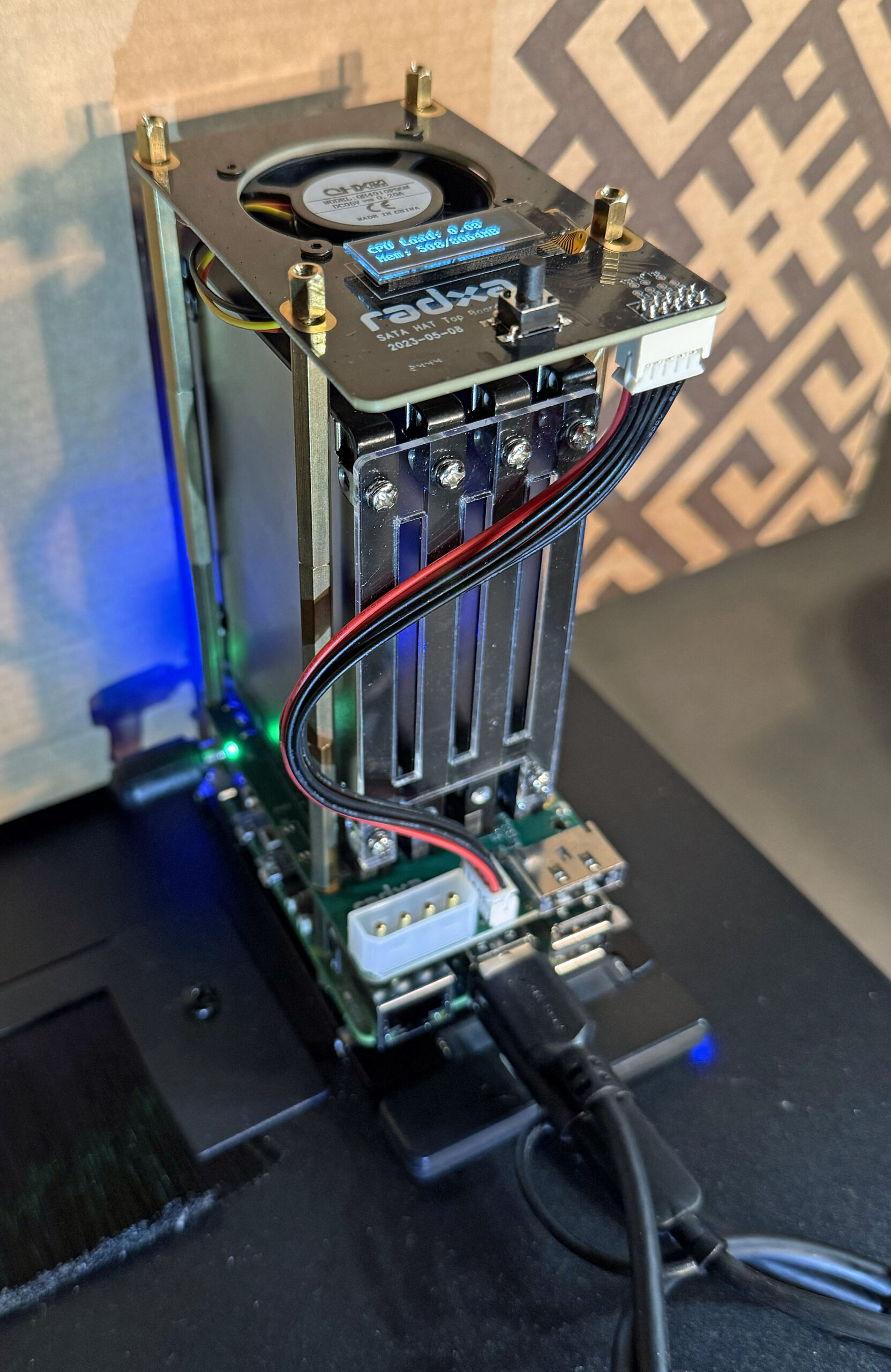
- A Radxa Penta SATA Hat which provides a “case” and mounting for four SATA drives
- A Radxa Penta SATA Top Board which adds a fan for cooling and a status display – is required to avoid overheating the components.
- A 12 Vdc, 10A Power Supply
- A Sabrent SATA to USB Cable to connect an additional SSD drive to hold the OS
- Five 960 GB SSD drives, four for storage and one additional for OS storage and boot.
I had five 960 GB 2.5″ SSD drives from a previous project available for this project.
The following video covers the hardware assembly –
We used a 2.5 GbE USB adapter to create a 2.5 GbE network interface on our NAS.
The configuration of the Fan/Display HAT top board is covered here.
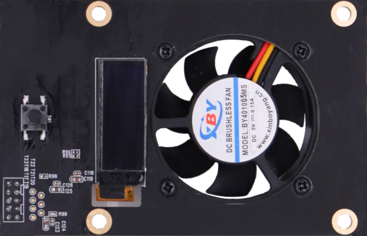
This board comes as a kit that includes spaces to mount it on top of the Raspberry Pi 5/SSD Drive Interface HAT in the base kit.
Software Components and Installation
We installed the following software on our system to create our NAS –
- Raspberry Pi OS 64-bit Lite Version – for system configuration and general applications
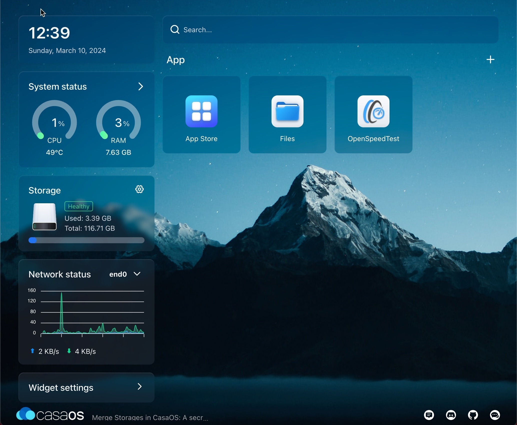
- CasaOS – for docker environment and container applications
CassaOS
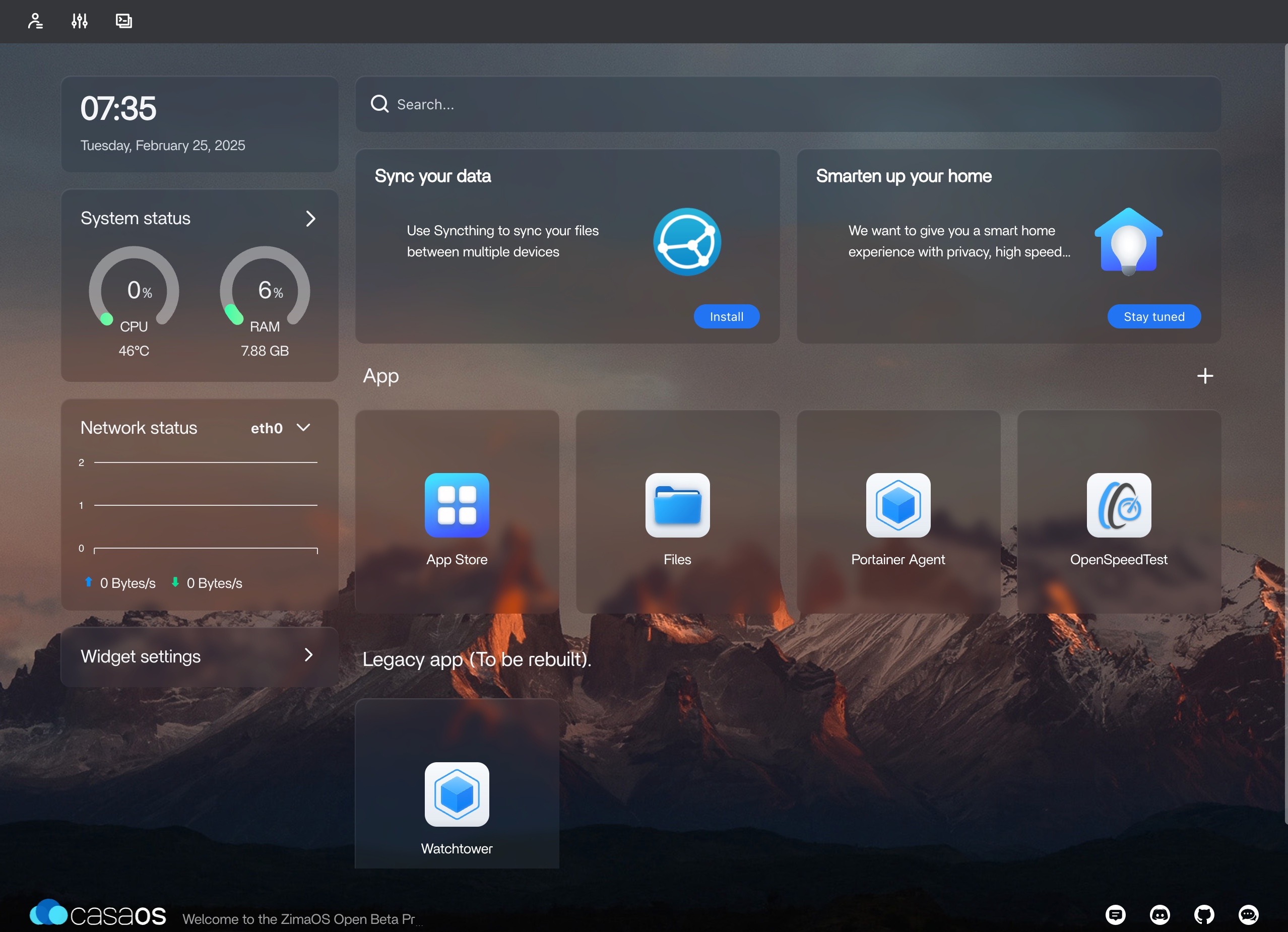
CasaOS is included to add a very nice GUI for managing each of our NUT servers. Here’s a useful video on how to install CasaOS on the Raspberry Pi –
Installation
The first step is to install the 64-bit Lite Version of Raspberry Pi OS. This is done by first installing a full desktop version on a flash card and then using Raspberry Pi Imager to install the lite version on our SSD boot drive. We did this on our macOS computer using the USB to SATA adapter and belenaEtcher.
We used the process covered in the video above to install CasaOS.
Creating a RAID
We choose to create a RAID-0 array using the four SSD drives in our NAS. Experience with SSD drives in a light-duty application like ours indicates that this approach will be reasonably reliable with SSD drives. We also backup the contents of the NAS daily to another system via Rsync to one of our Synology NAS drives.
CasaOS does not provide support for RAID so this is done using the underlying Linux OS. The process is explained here.
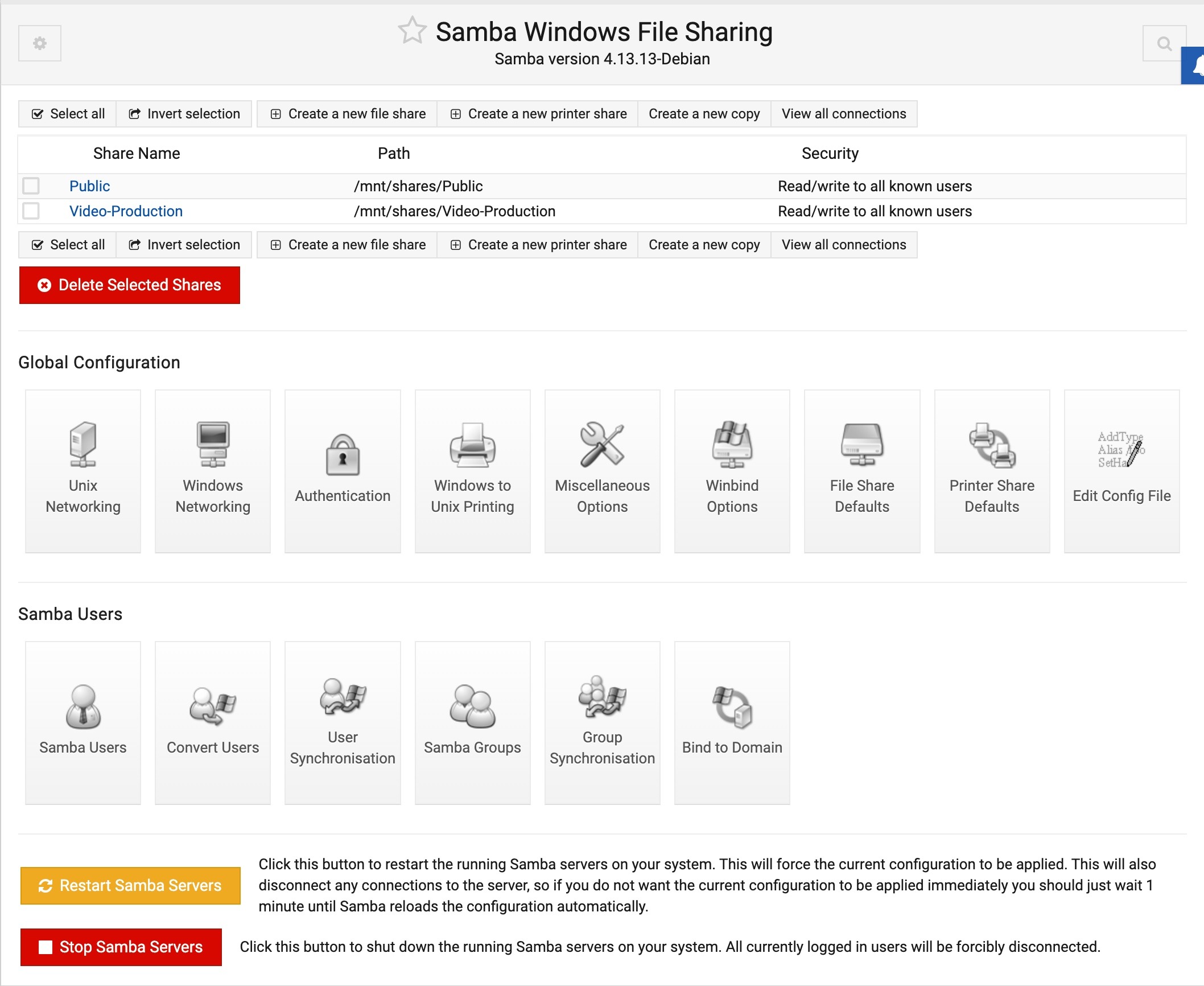
File Share
CasaOS makes all of its shares public and does not password-protect shared folders. While this may be acceptable for home use where the network is isolated from the public Internet, it certainly is not a good security practice.
Fortunately, the Debian Linux-derived distro we are running includes Samba file share support, which we can use to protect our shares properly. This article explains the basics of how to do this.
Here’s an example of the information in smb.conf for one of our shares –
[Public]
    path = /DATA/Public
    browsable = yes
    writeable = Yes
    create mask = 0644
    directory mask = 0755
    public = no
    comment = "General purpose public share"
You will also need to create a Samba user for your Samba shares to work. Samba user privileges can be added to any of the existing Raspberry Pi OS users with the following command –
# sudo smbpasswd -a <User ID to add>
It’s also important to correctly set the shared folder’s owner, group, and modes.
We need to restart the Samba service anytime configuration changes are made. This can be done with the following command –
# sudo systemctl restart smbd